Uncategorised

XE-SC (Simulation Cut) generates a Spice-simulatable netlist containing all paths between user specified start and end net(s). XE-SC inputs a hierarchical schematic spice netlist and an optional extracted dspf netlist, automatically derives circuit properties and logical equations for each net and transistor in the netlist, and stores these data in XE-Core engine. Designers use python and XE-SC's APIs to generates a spice deck containing all the paths between their specified start and end net(s). Unique sensitization output files can be optionally generated.

Some XE-SC features includes:
- Fast or slow cut path
- Auto sensitization
- Cap and Voltage Control Voltage Source side load model
- Prelayout netlist cut
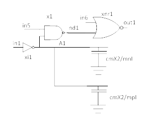
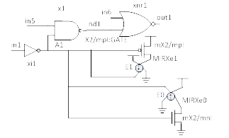
The following is an example of a simple nand-nor cut from in1 to out1. x2's transistors are modeled as side loads.
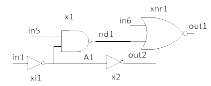
|
Cut with Capacitance side load
|
Cut with Voltage Control Voltage Source side load
|
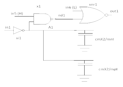
With auto sensitization, XE-SC auto sensitizes in5 as high and in6 as low to ensure signal on in1 is propagated to out1.
![]()

- Consistent pre-layout and post-layout analysis where the only differences are in parasitic values
- Hierarchical post-layout analysis where blackboxing the post-layout data of the lower level blocks
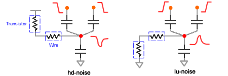
- Calculate 4 types of CCNs: high-up, low-up, high-down, low-down
- Noise tolerance on a victim net depends on its driver and receiver types.
- Calculate noise contribution from each individual aggressor. Defined by user-directives
- Calculate aggressor’s edge rates based on its driver Weff and load caps.
- Handle exclusive/complementary relations among aggressors and victim.
- Scripts available to automatically characterize technology data for CCNA.

YX Technologies® provides XE® software to analyze and abstract complex VLSI circuits. XE, an all-in-one EDA tool, works at the transistor level to analyze circuits for quality and reliability issues, check and report circuits violating design methodology rules, and create logical models at various abstraction levels for a full-custom design. The all-in-one nature of XE has been enabling many circuit design teams to deliver full-custom VLSI products quickly, reliably, and cost effectively.
![]()
XE-CCNASC (Capacitive Coupling Noise Analysis Simulation Cut) generates a Spice-simulatable netlist along with control file that includes the complete context of a victim and aggressors for Spice simulation. XE-CCNASC inputs a hierarchical shcematic spice netlist and/or exracted dspf netlist, automatically derives circuit properties and logical equations for each net and transistor in the netlist, and stores these data in XE-Core engine. XE-CCNASC then generates spice deck based on victim node and aggressor nodes identified by corresponding coupling capcitance from the victim node. Unique simulation control files will be generated for 4 different types of CCNs: high-up, low-up, high-down, low-down.

A circuit can be a victim or aggressors, and following is an example of a victim and an aggressor in a cut which describes how CcnaSc generats a circuit from original input schematic netlist.
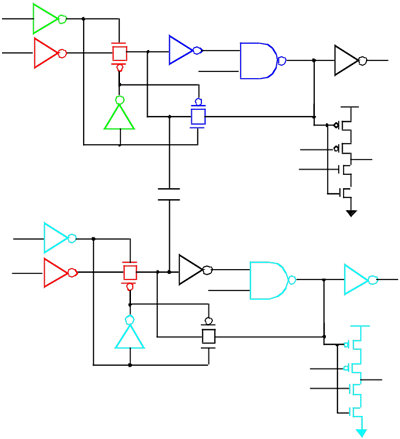 |
A Circuit can be a Victim or Aggressors: Victim: Driver and feedback loop.
Modeling of Load devices for vimctim and aggressor:
|
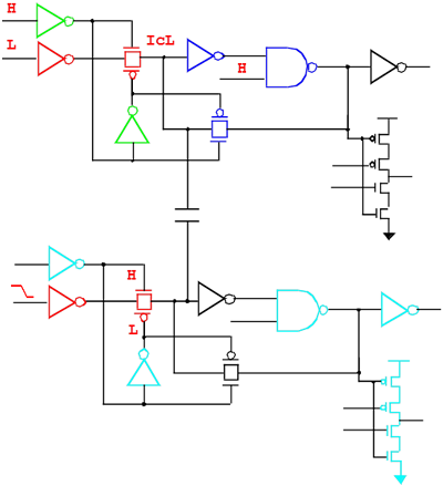
Following circuit with label shows example of sensitizing a state node (LU Noise).
 |
Sensitization Types
For Victim:
For Aggressors:
|
